![2BTech_FavIcon-WHITE-OUTLINE.png]](https://kb.2btech.io/hs-fs/hubfs/2BTech_FavIcon-WHITE-OUTLINE.png?height=1412&name=2BTech_FavIcon-WHITE-OUTLINE.png)
Technical Note No. 023
Model 400 NO Monitor Pump Upgrade
Date: 24 February 2010
Author: Stanley Strunk
Overview:
This amendment to the Model 400 user manual describes the changes made to the
model 400 NO monitor and the procedures to set the flows of the instrument. A
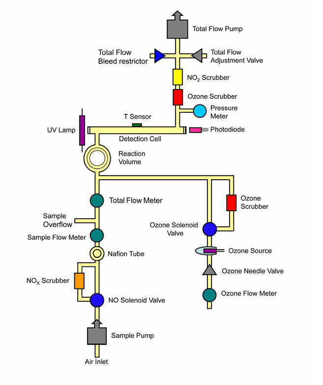
schematic diagram of the revised 400 can be seen below in Fig. 1 below. The total flow
and the ozone flow of the instrument are now pulled by a Sensidyne Model AA vacuum
pump with Viton diaphragm (top of diagram). There is no longer a separate pump for
the ozone flow, nor does the instrument push the total flow through the instrument. This
configuration allows for fewer pumps and greatly reduces the restriction on the total
flow/ozone pump. There is a bleed valve at the inlet of the total flow/ozone pump to
allow for coarse total flow adjustments. The ozone flow still has a needle valve
accessible from outside the instrument case for adjusting the ozone flow and now has
an added flow meter to measure the ozone flow directly. A duty cycle has been added
to the sample flow pump to allow less restriction on this inlet pump. There still remains
an internal needle valve on the sample flow pump to allow for coarse sample flow
adjustments. The firmware has been modified to accommodate these changes.
Setting flow rates and expected duty cycles:
The optimal flow rates for the instrument remain the same as before. The sample flow
should be 900-1100 cc/min volumetric. The total flow should be 570-630 cc/min
volumetric, and the ozone flow should be 20-30 cc/min volumetric. The default duty
cycle for the total flow pump is 50% and will go to this duty cycle when in flow mode in
the service menu. The sample flow duty cycle will go to 60% in this same menu. Once
in parameter adjustment mode, if the instrument is in auto adjust mode, the instrument
will attempt to set the total flow in the range of 570-630 cc/min. It will also set the
sample flow to 900-1100cc/min by adjusting the respective pump duty cycles. A floor
duty cycle is set at 42% for both pumps. A lower duty cycle will cause the flows of the
instrument to become unstable. Under normal operating conditions, the user can expect
these duty cycles to be 50-70%. If the instrument cannot adjust the flows into these
respective ranges, go to the flow mode in the Svc menu by holding down the select
knob while powering the instrument. Once in the Svc menu, select Tst then Flw. This
will display all 3 flows of the instrument and reset the total flow and sample flow duty
cycles to 50 and 60%, respectively. Using the needle valves on the back one can
adjust the total flow and ozone flow. Since the total flow pump uses a bleed valve, open
the valve further (turn counter clockwise) to lower the total flow and close the valve
further (turn clockwise) to increase the flow. To adjust the ozone flow rate, open the
valve further to increase the flow (turn counter clockwise) and close the valve further
(turn clockwise) to lower the ozone flow. If the sample flow needs manual adjustment,
the top cover of the instrument needs to be removed by first removing the faceplate and
bezel and then unscrewing the top plate from the back plate. Once the top is removed
the needle valve immediately following the sample flow pump can be adjusted. Do not
tighten this needle valve all the way closed, as that will cause pump failure. The further
open this needle valve is, the less strain on the sample flow pump there will be. If the
sample flow is greater then 1100 cc/min, but the 400 is not being used with a model 401
NOx converter, it is recommended to leave the sample flow needle valve as is. This
higher sample flow rate will have no effect on the measurements being made.