![2BTech_FavIcon-WHITE-OUTLINE.png]](https://kb.2btech.io/hs-fs/hubfs/2BTech_FavIcon-WHITE-OUTLINE.png?height=1412&name=2BTech_FavIcon-WHITE-OUTLINE.png)
Technical Note No. 043
Procedure for Decreasing “PDVs” on the Model 405 nm NO2/NO/NOx Monitor
Date: 6 Jun 2019
Author: Brian Carpenter
Summary:
This Technical Note shows you how to decrease the photodiode voltage produced by the
LED of your Model 405 by adding a small light barrier to the cell window. This procedure
should only be used if you notice the sample photodiode voltage (“PDVs” in the serial
data stream) is maxed out at 2.49999 and you are unable to return the unit to the factory
for repair.
1. Remove the top cover.
2. Turn instrument on its side and remove screws.
3. Remove LED.
4. Cut a piece of electrical tape.
5. Place tape piece on plastic aperture covering some of hole, or on center of cell
window, to block some of the light coming from LED.
6. Reinstall LED.
7. Check PDVs on serial data stream.
8. Reinstall all screws and top cover.
Tools needed:
• Phillips Head Screwdriver
• Electrical Tape
• X-Acto Knife or Razor Blade
• Optional: Tweezers
Procedure:
Power off and unplug your instrument before proceeding.
1.) Remove top cover to instrument by removing top three screws on both sides of
instrument:
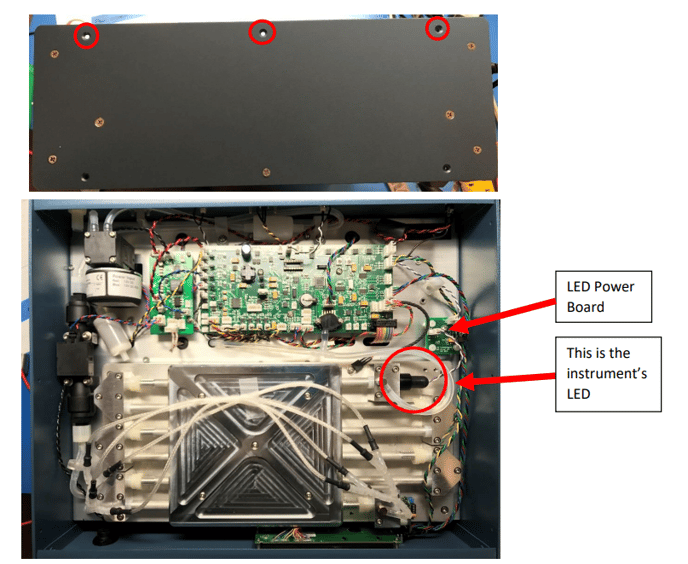
The top of your instrument with the cover removed should look similar to this.
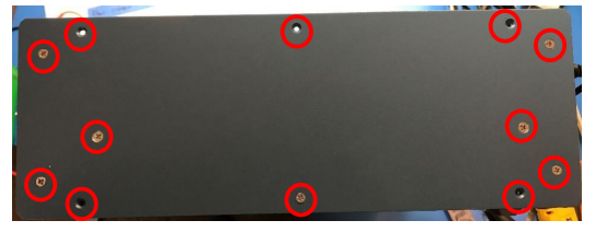
2.) Next, turn the instrument so it’s LEFT side (the side away from the LED) is on the
bottom, then remove the rest of the screws.
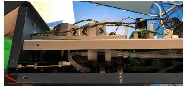
The side of the instrument should now look similar to this
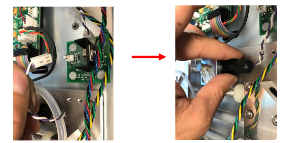
3.) Remove the instrument’s LED. First, unplug the wire from the LED power board
(see figure in Step 1). Next, unscrew the LED from the cell by turning it
counterclockwise.
4.) Look at where the LED was screwed into, it will either look like picture A or
picture B; this will determine how you proceed. If the LED Housing Cube looks
like picture A (with a plastic aperture installed) then proceed to the next step
(step #5) and complete steps 5 ̶9. If the Cube looks like picture B, then skip to
step #10 and complete steps 10 ̶14.
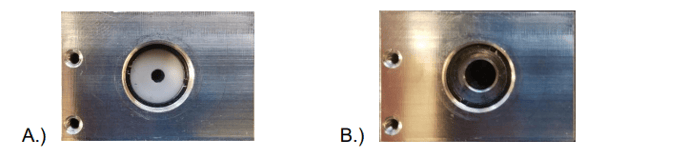
IF YOUR HOUSING CUBE LOOKS LIKE PICTURE “4A” FOLLOW STEPS 5-9.
IF YOUR HOUSING CUBE LOOKS LIKE PICTURE “4B”, SKIP TO STEP 10.
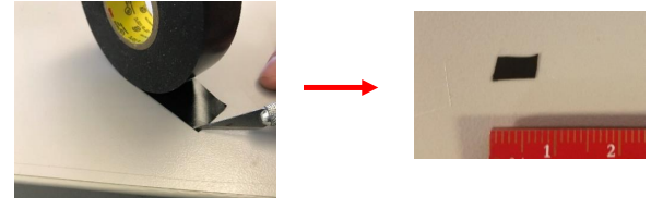
5.) Cut a small rectangular piece of electrical tape with either an X-Acto knife or a
razor blade. The size of this rectangle should be about 6mm X 3mm.
6.) Using Tweezers or the tip of an X-Acto knife, 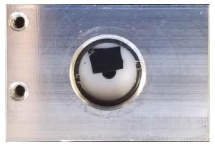
lightly place the sticky end of the electrical
tape onto the plastic aperture to cover ~1/4 of
the hole. The goal is to block some of the
light coming from the LED. Refer to the photo
at right.
7.) Reinstall your LED by reversing what you did
in step #3 (only tighten the LED to hand-tight).
8.) Prior to reinstalling all of the enclosure screws, plug in your instrument and
connect the Serial to your computer. Turn the instrument on and view the data
stream which should look something like this:
Avg: 5 s/rdg
NO2,NO,NOx,ZNO2,ZNO,Tc,P,Fc,Foz,PDVs,PDVg,Ts,Date,Time,Mode
0.0,0.0,0.0,0,0,23.9,765.0,1626,68.2,1.002128,0.041,38.2,16/08/17,14:44:57,80
The value for “PDVs” is what you will be looking at. This value should now be
somewhere between 0.7 and 1.7. If the value is lower than 0.7 make your piece
of electrical tape cover less of the hole on the aperture. If the value is above 1.7
move the electrical tape so as to cover more of the aperture hole.
9.) Now that the photodiode voltage produced by your LED is in the correct range,
reinstall the screws securing the side panel starting with the centermost two
screws (do not overtighten the screws - they only need to be hand-tight). Note:
be careful not to crush any of the wires in-between the side panel and the
baseplate. Next, install the four screws which secure the side plate to the front
and back plates. Finally, install the three screws which secure the bottom cover,
then reinstall the top cover and add the remaining screws
FOLLOW STEPS 10-14 IF YOUR HOUSING CUBE LOOKS LIKE PICTURE 4B.
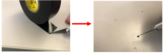
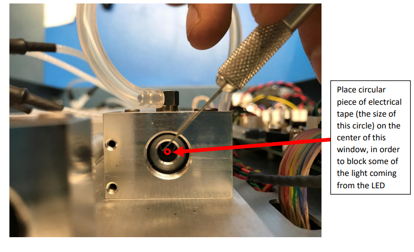
10.) Cut a small corner off a piece of electrical tape with either an X-Acto knife or
razor blade (try to make the piece as circular as possible). The diameter of this
circular piece of electrical tape should be ~1.5 mm.
11.) Lightly place the sticky end of the electrical tape onto the window of the cell
(where the LED was screwed into) using Tweezers or the tip of an X-Acto knife
(being VERY careful not to scratch the window). The circular piece of electrical
tape needs to be in the CENTER of the circle.
12.) Install your LED by reversing what you did in step #3 (only tighten the LED to
hand-tight).
13.) Prior to reinstalling all of the screws plug in your instrument and connect the
Serial to your computer. Turn the instrument on and view the data stream which
should look something like this:
Avg: 5 s/rdg
NO2,NO,NOx,ZNO2,ZNO,Tc,P,Fc,Foz,PDVs,PDVg,Ts,Date,Time,Mode
0.0,0.0,0.0,0,0,23.9,765.0,1626,68.2,1.002128,0.041,38.2,16/08/17,14:44:57,80
The value for “PDVs” is what you will be looking at. This value should now be
somewhere between 0.7 and 1.7. If the value is lower than 0.7 make your circular
piece of electrical tape very slightly smaller. If the value is above 1.7, put on a
circular piece of electrical tape that is very slightly larger.
14.) Now that the photodiode voltage produced by your LED is in the correct range,
reinstall the screws securing the side panel starting with the centermost two
screws (do not overtighten the screws - they only need to be hand-tight). Note:
be careful not to crush any of the wires in-between the side panel and the
baseplate. Next, install the four screws which secure the side plate to the front
and back plates. Finally, install the three screws which secure the bottom cover,
then reinstall the top cover and add the remaining screws